
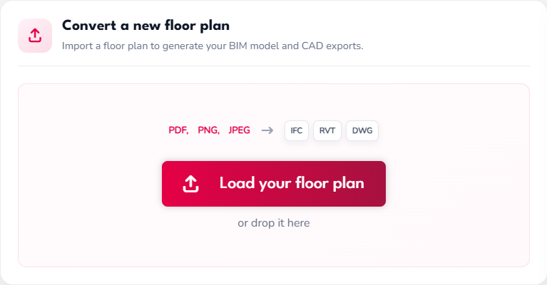
Import a single-page or multipage PDF. Where available, use a vector export from the drawing software: text and lines can retain information useful for analysis.
01 · Getting started
The conversion workflow
AmpliFY converts the graphical information in an architectural floor plan into model elements: walls, openings, rooms, slabs and objects. You can view the result, correct its geometry in the editor and generate files to continue working in your BIM or CAD tools.
The workflow is primarily designed for residential floor plans. Results depend on the clarity of the document, how elements are drawn and the accuracy of the scale.
Sign in before starting generation. Available actions and usage limits depend on your account.
- Import your floor plan using “Load your floor plan” or drag and drop.
- Confirm the building area and scale for each plan. Use a known distance to resolve any uncertainty about dimensions.
- Prepare the storeys: add the required plans and arrange them from lowest to highest.
- Click “Start AmpliFY” to generate the model.
- Compare the result with the plan, then open the editor to make corrections.
- Check that your changes are saved and export to IFC, RVT or DWG as needed.
Check the scale
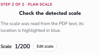
Even correctly recognised geometry can have the wrong dimensions if the scale is incorrect. Verify a reference dimension before generation, then check it again in the model.
02 · Source document
Supported formats and plan preparation
PNG or JPEG
Import a clear, undistorted image. Its pixel dimensions do not establish the building’s real dimensions: have a known reference length ready.
The file picker accepts multiple files. A multipage PDF can group several storeys; check which plans have actually loaded before starting. Upload and storey limits depend on your account access.
Source document quality
- Use a straight floor-plan view with readable lines and sufficient resolution.
- Prefer one storey per page and a clearly identifiable building area.
- Avoid perspective photographs, skewed scans, heavy compression and annotations that obscure walls or openings.
- If a page contains several buildings or scales, prepare separate imports with consistent areas.
- Keep dimensions and the title block legible: they help you verify the scale.
Vector PDF and scanned PDF
A vector PDF can contain directly usable lines and text. A scanned PDF mainly contains an image, so reading its labels depends on text recognition. The PDF format alone does not guarantee source quality.
03 · Plan review
Building area and scale calibration
Confirm the area to process
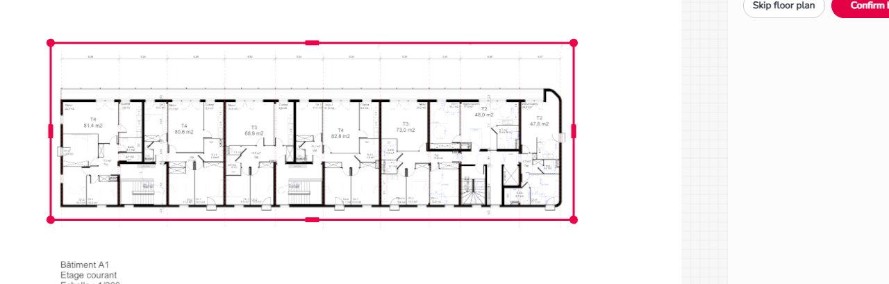
AmpliFY proposes a building detection area. Drag the frame handles to include everything to reconstruct, without including another plan, a legend or details unrelated to this storey. Check balconies, external walls and annexes before confirming.
Where the scale comes from
| Displayed source | Meaning | What to check |
|---|---|---|
| Title block or PDF text | A scale was read from the document; its location may be highlighted in blue. | Check that it applies to the selected plan and that the document has not been resized. |
| Automatic estimate | The scale was estimated from the graphical content. | Check it against a known length. |
| Provisional value | If estimation fails, the interface may suggest 1:100 as a provisional value. | Correct or confirm it with a measurement before continuing. |
Correct the scale using a measurement
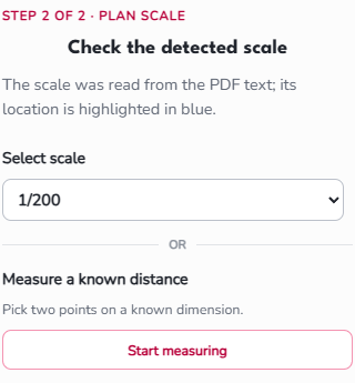
- Activate scale correction by measurement.
- Select both ends of a length whose real value you know.
- Enter that value using the unit shown in the interface.
- Check the result, ideally against another dimension elsewhere on the plan.
For a PDF, you can also correct the scale using the available selection. For a PNG or JPEG, correction requires measuring a known distance. Use a long dimension and precise points: a small click error represents a larger proportion of a short distance.
Scale affects both lengths and areas.
A scale error that doubles lengths multiplies areas by four. Changing a storey height does not correct this horizontal error.
04 · Multistorey projects
Set up storeys before generation
Select both PDFs in the same import: Plan-demo-Ground-floor.pdf and Plan-demo-First-floor.pdf. Review the building area and scale of each plan, then check both entries in the project overview. The examples use one project containing both storeys, generated together. Drag the plan entries into bottom-to-top order: ground floor as GF, then first floor as L1. File-name order may differ from storey order. Set the starting level and start AmpliFY only after both plans are ready.
- Arrange plans from the lowest level to the highest.
- Check that no cover page, section or alternative drawing is being treated as a storey.
- Check each plan’s scale separately: pages in the same PDF can have different scales.
- Start AmpliFY when the list matches the building to reconstruct.
This list establishes the sequence of storeys. After generation, you can adjust their names, elevations, slab thicknesses and horizontal alignment.
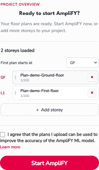
Choose whether your plans can help improve the model
The overview includes a consent checkbox allowing uploaded plans to be used to improve the machine learning model. Read this choice and the “Learn more” link before starting. This checkbox is left unchecked in the illustrated workflow.
05 · Plan processing
How the model is generated
AmpliFY combines detection models with geometric processing. Recognition identifies likely elements; reconstruction turns them into structured objects and corrects some inconsistencies between them.
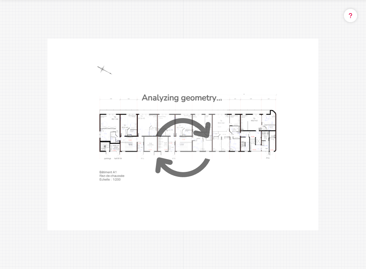
1. Prepare the plan for analysis
Processing uses the confirmed area and scale to prepare the plan for analysis. Image coordinates remain linked to metric dimensions so the result can be overlaid on the source document and reconstructed objects can be sized correctly.
2. Detect architectural elements
AI models produce detections and segmentation masks. A detection locates an element; a mask describes the image area it occupies. These results help identify walls, rooms, openings and supported object families. See the complete recognition catalogue below.
3. Reconstruct walls and spaces
Detected regions become lines, thicknesses and polygons. Processing merges some duplicates, simplifies outlines, adjusts wall junctions and handles interactions between walls and rooms. Columns are also distinguished during reconstruction.
This explains why the final outline can differ slightly from the initial mask: it reflects both detection and reconstruction rules. The engine can also adjust geometry to PDF vector lines in some workflows; this option should not be assumed to run in every case.
4. Attach openings and read room labels
Doors and windows are associated with walls to establish their openings and dimensions. AmpliFY first tries to read room labels from PDF text. Where this fails and detection data allows it, OCR reads the image instead.
An unreadable label can leave a room incorrectly named even when its outline is correctly reconstructed. Check geometry and labels separately.
5. Build volumes from 2D geometry
Outlines become volumes using height, sill height and slab thickness settings. Storeys are positioned within the project, with alignment processing seeking to match their plans. The resulting model retains identifiable elements, their properties and their level assignments.
6. Display, assess and prepare for editing
The web app loads model data and builds the interactive browser scene. Generation and export processing run on the server. Available scores help identify elements that need closer inspection.
Detected, reconstructed and configured: three different sources.
A wall’s position comes from plan analysis; its junction with another wall may be adjusted during reconstruction; its height depends on project settings. A floor plan alone does not describe every characteristic of the building in three dimensions.
Which elements can AmpliFY recognise?
The catalogue below covers the element families recognised during plan processing. Recognition depends on the drawing, its scale and the clarity of its symbols; a supported element can still be missed or misclassified. Object inclusion settings also determine what appears in the generated model.
| Element | What AmpliFY recognises and reconstructs |
|---|---|
| Walls and partitions | AmpliFY recognises interior and exterior walls, including thick walls and thin partitions. It assigns one of two default wall types: Generic for interior walls or Exterior for exterior walls. Reconstruction estimates their position and overall thickness and connects junctions. Individual wall layers and their materials are not recognised. Structural load-bearing roles are not established by these detection classes. |
| Columns | Column footprints, distinguished from ordinary walls during reconstruction. |
| Doors | Door openings attached to walls. Readable leaf and swing symbols help establish single or double doors and their opening direction. Door uses, such as elevator or landing doors, can be inferred from the surrounding spaces. |
| Windows | Window openings attached to walls. Their plan position and width come from the drawing; sill height and height use the generation settings. |
| Closet fronts | Closet door fronts help reconstruct the boundary of a storage space. A recognised front is not a detailed cabinet model or a guarantee that each sliding or hinged panel becomes an editable door. |
| Toilets | WC fixtures, independently of the category assigned to the room containing them. |
| Washbasins and sinks | Bathroom basins and kitchen sinks, using the same detection family. |
| Showers | Shower footprints represented by an equipment object. |
| Bathtubs | Bath footprints represented by an equipment object. |
| Beds | Bed footprints. Recognition of beds does not imply automatic recognition of every other furniture type. |
| Kitchen elements — beta | Kitchen equipment footprints. Excluded by default; enable them in Generation preferences and check the result. This is separate from recognising a room as a Kitchen. |
| Stairs — beta | Stair object footprints. Excluded by default; enable them in Generation preferences and check the result. Recognising a Stairwell space does not require this option and does not guarantee a detailed staircase model. |
Rooms and space categories
AmpliFY recognises room regions, reconstructs their boundaries and assigns a category. The visual recognition categories are:
- Living spaces: Living Room, Kitchen and Bedroom.
- Sanitary and storage spaces: Bathroom, Toilet and Storage.
- Circulation and vertical access: Hallway, Common Circulation, Elevator and Stairwell.
- Other regions: Outdoor Area (such as a terrace), Shaft and Undefined.
Reading the room labels can refine this classification and identify five additional standard categories: Laundry, Bicycle Room, Technical Room, Maintenance Room and Waste Room. These are not separate visual object families. Undefined means that a region has no established room category; it can still have a usable outline.
An Elevator region describes the elevator space, not its mechanical equipment. Similarly, a Toilet room and the WC fixture inside it are separate elements. Check recognised text, category and geometry independently, then correct or create categories in the editor when needed.
Recognition limits and generated elements
Floor slabs, the upper closing slab and slab openings are generated from the reconstructed layout and generation preferences; they are not separate detected equipment families. Heights and other vertical dimensions come from settings rather than a complete reading of the floor plan.
Generic objects and custom free shapes let you represent additional elements manually. A shape or model available in the editor does not mean that AmpliFY automatically detects it. Likewise, recognition does not imply support in every export format; see Exporting the model.
06 · Model settings
Generation settings and assumptions
Open “Generation preferences” from the account menu. Configure and save these values before processing your next plans. For an existing model, use project settings and editor properties to adapt the result.
| Setting | Initial value | Purpose |
|---|---|---|
| Level height | 3.00 m | Set the default height of levels. |
| Slab thickness | 0.20 m | Give generated floor slabs a thickness. |
| Window sill height | 0.70 m | Position the bottom of windows above the level. |
| Window height | 1.50 m | Set the height of window openings. |
| Door height | 2.05 m | Set the height of door openings. |
These are starting assumptions. Replace them with project dimensions where known. Follow the displayed units and limits; settings must remain geometrically consistent, especially opening heights relative to the available height.
Generation language
Choose English or French in the preferences. This controls generation; the web app’s EN/FR selector controls the interface language. This guide uses the English interface labels.
Slab openings
Choose where to cut slabs: nowhere, in shafts only, in lifts and stairs, or in all three categories. An option excludes the first level’s slab from these cuts. The initial configuration enables cuts in all three categories without excluding the first level.
Included objects
Enable or disable toilets, washbasins and sinks, showers, bathtubs and beds. Kitchen elements and stairs are in beta and are excluded by default. If enabled, check their presence and shape carefully.
07 · Reviewing the result
Inspect the model in 2D and 3D
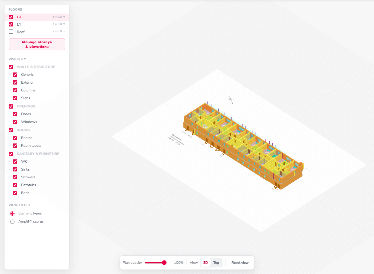
Plan view
Compare walls, room outlines and openings with the source plan. This is particularly useful for checking junctions, offsets and missing elements.
3D view
Inspect the assembled storeys, heights, openings and slabs. Reset the camera if the building moves out of view.
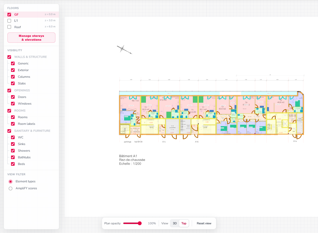
- Floors: select the active level and show or hide others to isolate the area you need to check.
- Category visibility: filter element families to make the view clearer.
- Opacity: adjust the source plan and modelled elements separately.
- Properties: select an element to inspect its available information.
- AmpliFY scores: use score colouring to guide your checks.
- Room labels: choose what to display in the editor settings.
How to read a score
The “AmpliFY scores” filter uses a scale from 0 to 1. A score helps prioritise checks; it does not measure dimensional accuracy. A score of 0.9 does not mean every dimension of an element is 90% accurate.
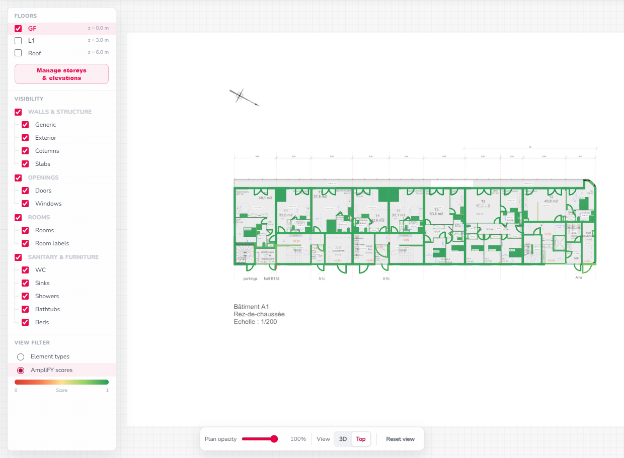
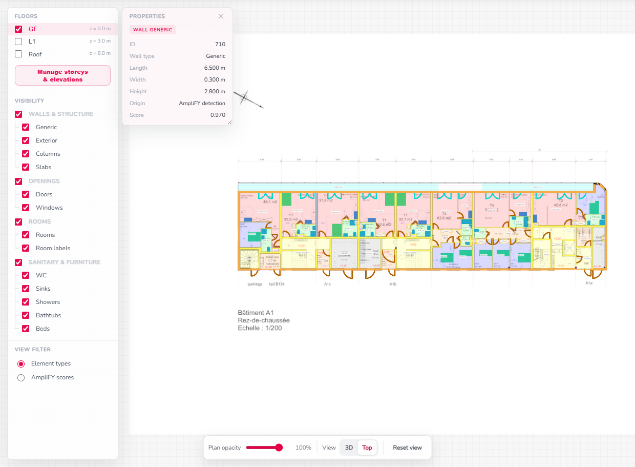
Hiding an element or reducing its opacity does not remove it from the model. Use the editing tools to delete an object from the project.
08 · Level positioning
Align storeys and adjust elevations
Names, elevations and thicknesses
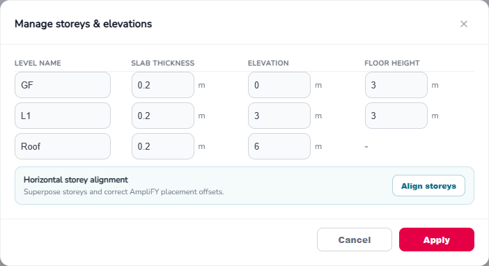
Open “Manage storeys & elevations”. The table lets you adjust level names, elevations and slab thicknesses while reviewing storey heights. Check the displayed units and apply changes when all values are consistent.
Elevation is a level’s vertical position. Storey height describes the interval between levels. It differs from the clear height below a slab, which also depends on structural thickness.
Horizontal alignment
During generation, AmpliFY attempts to align storeys automatically by identifying corresponding stair and lift areas on their plans. It compares these shared reference areas and looks for a horizontal offset that superposes them, bringing the storeys into alignment.
Automatic alignment can fail or produce an incorrect offset, particularly when these areas are missing, incorrectly recognised or difficult to match between plans. Check the result after generation. If the storeys do not line up, use “Align storeys” to adjust their horizontal positions manually.
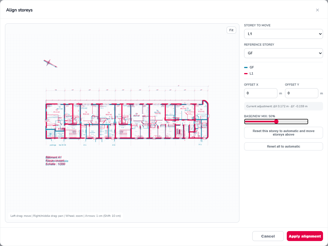
The example below uses the ground floor as the reference and the first floor as the level to move. This is a horizontal adjustment, separate from the elevation and height values in the preceding table.
- From “Manage storeys & elevations”, click “Align storeys”, then select the storey to move and the reference storey.
- Adjust the blend between the plans to find a reliable common point: an external corner, stairwell or shaft.
- Move the target plan or enter its X and Y offsets. In this dialog, arrow keys move it by 1 cm; Shift + arrows move it by 10 cm.
- Check a second reference point far from the first, then apply the alignment.
Movement propagates to upper storeys.
When you move a storey, the same offset is applied to the levels above it. Work from bottom to top and check the entire stack. Resetting a storey to its automatic alignment can also move upper storeys.
This adjustment corrects a horizontal translation. If one reference point aligns but another does not, check plan scale and orientation: movement alone cannot correct a difference in size or distortion.
09 · Project creation and storage
Create, save and reopen a project
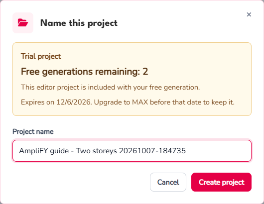
A generated result lets you inspect the model and prepare exports. To keep an editable project in your account, click “Review & edit model”, give the project a name and confirm “Create project”. In this example, the ground floor and first floor become two storeys of the same project.
Simply viewing a generated result does not create a saved project. Create the project to save your work and return to it later.
What is saved?
The project keeps its storeys, source plans, model geometry and editable properties. Wall types and room categories belong to the project and are shared across its storeys. After creation, edits trigger automatic saving.
- Pending…: changes are waiting to be saved.
- Saving…: a save is in progress.
- Saved: the latest changes have been saved.
- Unsaved changes: saving failed; resolve the displayed error before leaving.
Wait for “Saved” before closing the tab. A lost connection can prevent saving even while the model remains visible.
Project saving with MAX and trial access
Project saving is included with MAX subscriptions, so you can reopen your projects and continue editing them later.
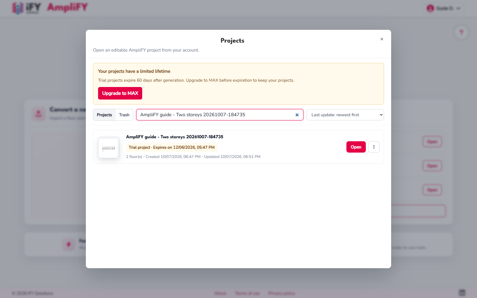
New users receive several trial projects to try this feature. These projects remain available for a limited time, allowing you to explore saving, reopening and editing before choosing MAX.
Find the project again
Use the recent projects on the home screen or open “Projects” from the account menu. The Project browser lets you search, sort, rename and reopen saved projects. Reopening restores the existing project so you can continue editing its storeys.
Trash and restoration
Deleting a project moves it to the trash, where it can be restored while it remains available. Permanent deletion and “Empty trash” cannot be undone.
A saved project and an exported file are separate.
IFC, RVT and DWG files describe the model at export time. Later edits do not update downloaded files. Temporary processing and export files have their own availability period, separate from project storage.
10 · Modelling tools
Editing elements
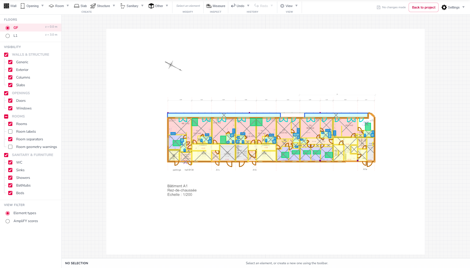
Open the saved project in the editor and choose the active storey in “Floors”. A visible storey is not necessarily the active one: check the active-floor control before creating or changing elements. Work on walls and openings first, then rooms, slabs and objects.
Select, move and inspect
Click an element to select it and display its properties. For rooms, click the room’s cross marker; for slabs, click the boundary. Use Shift + click or Ctrl + click to extend the selection. A rectangle drawn left to right selects fully contained elements; right to left also includes intersected elements. For mixed selections, “Filter selection” narrows the selection to the families you need.
Drag the selected element or its available handles to adjust position and geometry. Use the properties panel for exact dimensions and supported shared properties. The “Modify” group changes with the selection: select one wall for Split, one opening for conversion and swing, objects for Rotate, or one slab for Edit slab.
Change several elements at once
A multiple selection displays properties grouped by element family. A shared value is shown normally; […] means the selected elements have different values for that property.
- For example, select three partition walls with Shift + click. If doors or other elements are also selected, use “Filter selection” to keep the walls, or use the cross on an unwanted property group to deselect that group.
- In the wall properties, click the underlined Thickness value. Enter 0.10 when the displayed unit is metres to give all three walls a thickness of 100 mm. Check the message showing how many walls will be modified.
- Press Enter or click outside the field to apply a number or text value. Press Escape or the field’s Cancel button before committing to discard it. Dropdown and boolean choices apply immediately; use Undo to reverse a committed change.
The new value replaces the value on every selected element in that property group. Editing the wall group does not change selected doors or rooms. Use the same method to assign one wall type or room category to several elements, then inspect the result and wait for “Saved”.
Create elements
| Tool or family | How to use it | Check afterwards |
|---|---|---|
| Wall | Choose Wall and place its endpoints. Set its thickness and type in the properties. | Endpoints, junctions and thickness against the plan. |
| Opening → Door / Window | Choose the opening and place it on its host wall. Adjust width, height and sill height in the properties. | Correct host, position, dimensions and swing. |
| Room / Room separator | Click inside a space to place a room origin; its outline is fitted to the surrounding boundaries. Draw a separator between two points where the boundary has no physical wall. | A closed room outline, an origin inside the intended space, correct name and category, and no unwanted overlap. |
| Slab | Draw the slab boundary, finish the outline and adjust its thickness. Add openings in slab editing. | Footprint, holes and relationship to the active level. |
| Structure | Add round or rectangular columns. | Section, dimensions and position. |
| Sanitary | Place a toilet, sink, shower or bathtub, then adjust dimensions and orientation. | Footprint and alignment with the source plan. |
| Other | Place a bed or generic rectangle, draw a generic free shape, or add a railing. | The outline and dimensions needed for your model. |
Follow the active tool’s placement preview and confirmation controls. Escape cancels the current operation or returns to selection, depending on the tool. “Settings → Keyboard shortcuts” lists the available constraints and shortcuts.
Adjust walls and their connections
Select one wall to reveal its endpoint and thickness handles. Drag an endpoint to change its length or direction. Bring it to a neighbouring wall’s endpoint or face to form a junction, using the snapping preview. Connected walls can adjust together when you move or resize one of them; inspect both sides of the junction and nearby openings afterwards.
- Move a wall: drag its body. Hold Shift for horizontal or vertical movement, or Ctrl to constrain a single wall to its own axis.
- Move an endpoint: hold Shift for horizontal or vertical alignment from the opposite endpoint, Ctrl to keep the current wall direction, or Alt to disable direction snapping.
- Disconnect an endpoint: hold U when releasing a moved endpoint to release its attachment without automatically attaching it at the new position. Check the resulting junction before continuing.
- Change thickness: drag a thickness handle to move one face while keeping the opposite face fixed. Hold Shift to move both faces symmetrically around the centreline. The Thickness field provides a precise numeric value.
For example, when matching an external wall to the plan, drag the inner face to correct its thickness while preserving the outer face. Use symmetric resizing when the centreline is already correctly positioned. Check the adjacent room outlines after either change.
Fit rooms and use separators
A room is defined from an origin point inside a space. AmpliFY fits its contour to the surrounding boundaries and recalculates affected rooms after wall or separator edits. The cross marker is the room origin: dragging it repositions the point used for fitting and the room label. The drag stays within the current room contour; it does not move the enclosing walls.
Example: separate a living area and dining area without adding a wall.
- On the active storey, check that the outside boundary of the combined space is closed. Repair gaps or incorrect wall junctions first.
- Choose “Room → Room” and click inside the living area to place an origin, unless a room already exists there. Inspect the fitted outline before adding another room.
- If needed, drag the existing origin to the living-area side of the intended division, keeping it inside the contour and away from walls.
- Choose “Room → Room separator” and draw a line between the enclosing boundaries at the division. A separator defines a room boundary without creating a physical wall. Check that the existing room now fits the living-area side.
- Place a new room origin on the dining-area side. Assign each room its category and Custom Label, then compare both contours and areas with the plan.
- Move a boundary or adjust the separator if the division is incorrect. Check the automatically updated contours and resolve any geometry warnings before exporting.
Resolve geometry warnings: enable “Room geometry warnings” in the visibility panel and hover over a “!” marker to read the reason. Hiding the warning does not correct the geometry.
| Warning | What to do |
|---|---|
| Room overlap | Check whether two origins describe the same space. Delete an unintended duplicate room, or complete the separator that should divide two different spaces. |
| Origin inside a wall | Move the cross into the intended clear space within the room contour. Check the wall position and thickness if the origin cannot be placed correctly. |
| No valid closed boundary, invalid polygon or wall overlap | Inspect gaps, crossing boundaries and misplaced walls or separators. Undo the last geometry change if needed, repair the boundaries and recheck the fitted contour. If fitting still fails, correct the enclosure before recreating the affected room. |
Measure
Choose “Measure”, click the start point, then click the end point. The displayed distance lets you compare the model with a known dimension on the source plan. Hold Shift to constrain the measurement horizontally or vertically. You can add several measurements; “Clear” removes them. Escape cancels an unfinished measurement or exits the tool.
Measuring checks the model; it does not recalibrate or resize it. Correct an incorrect scale through the plan calibration workflow.
Copy and Split
Copy (C): select supported walls, openings, rooms or objects, click Copy, move the placement preview and click to place the duplicate. The original remains in place. Check the destination storey and, for copied openings, the receiving wall. Escape cancels before placement.
Split (X): select one wall, activate Split and click the required cut position on the wall. This creates separately editable wall segments. Inspect the junction and nearby openings afterwards.
Resize and rotate objects with handles
Select one object to show its width, depth and rotation handles. Drag a side handle to resize its footprint; the opposite edge stays fixed. Hold Ctrl while resizing to preserve the width-to-depth ratio, or Shift to resize symmetrically around the centre. These are separate modes: Shift takes precedence when both keys are held.
Drag the rotation handle to turn the object around its pivot. Hold Shift to snap to 90° increments, or Alt to disable rotation snapping. For precise values, enter Width, Depth, Height or Angle in the properties panel. For example, Ctrl + drag enlarges a bed while keeping its proportions; Shift + drag on a side handle changes its footprint around the same centre.
Rotate, convert openings and invert swing
Rotate: select an object and click Rotate, or press Space, to turn it by 90°. Repeat to reach the desired orientation. Rotation changes orientation; use the dimension fields to resize the object. Eligible custom free shapes also offer “Flip” to mirror their shape.
To Window / To Door: select one door or window and use the conversion button. It changes the opening’s family while keeping it associated with its wall. Check its height, sill height and dimensions after conversion.
Invert swing: with one opening selected, use “Swing” or Space to cycle its opening orientation. For a door, compare the hinge side and swing arc with the plan; repeat until they match. This changes the opening orientation rather than rotating its host wall.
Adjust opening dimensions and symbols
Select one door or window. Drag its body to adjust its position along the host wall, or drag an end handle to change its width while keeping the opposite end fixed. Openings follow their wall’s direction. Use the properties panel for the remaining settings.
| Property | Use |
|---|---|
| Width / Height / Sill height | Set the opening dimensions. For windows, Sill height positions the bottom above the storey level; check that sill height plus window height fits below the slab. |
| Type | For doors, classify the use as Interior, Exterior, Landing, Closet or Elevator. To change a door into a window, use “To Window”. |
| Symbol | Choose the leaf arrangement: None, Left, Right, Double or an asymmetric double symbol. None removes the swing symbol while keeping the opening. |
| Swing angle / Flipped / Double action | Set the angle shown by the swing, flip it to the other side of the wall, or show a swing on both sides. Compare the resulting symbol with the source plan. |
| Depth offset % | Position the door or window within the wall thickness. Zero centres it; positive and negative values shift it towards opposite faces. Check the result after flipping the opening, which also reverses the offset direction. |
For example, correct a window’s Width, Height and Sill height, then inspect it in 3D to confirm its placement. Use the plan view to check its position and opening symbol. Export support for these properties depends on the format; see the Revit export explanation.
Edit a slab outline and its openings
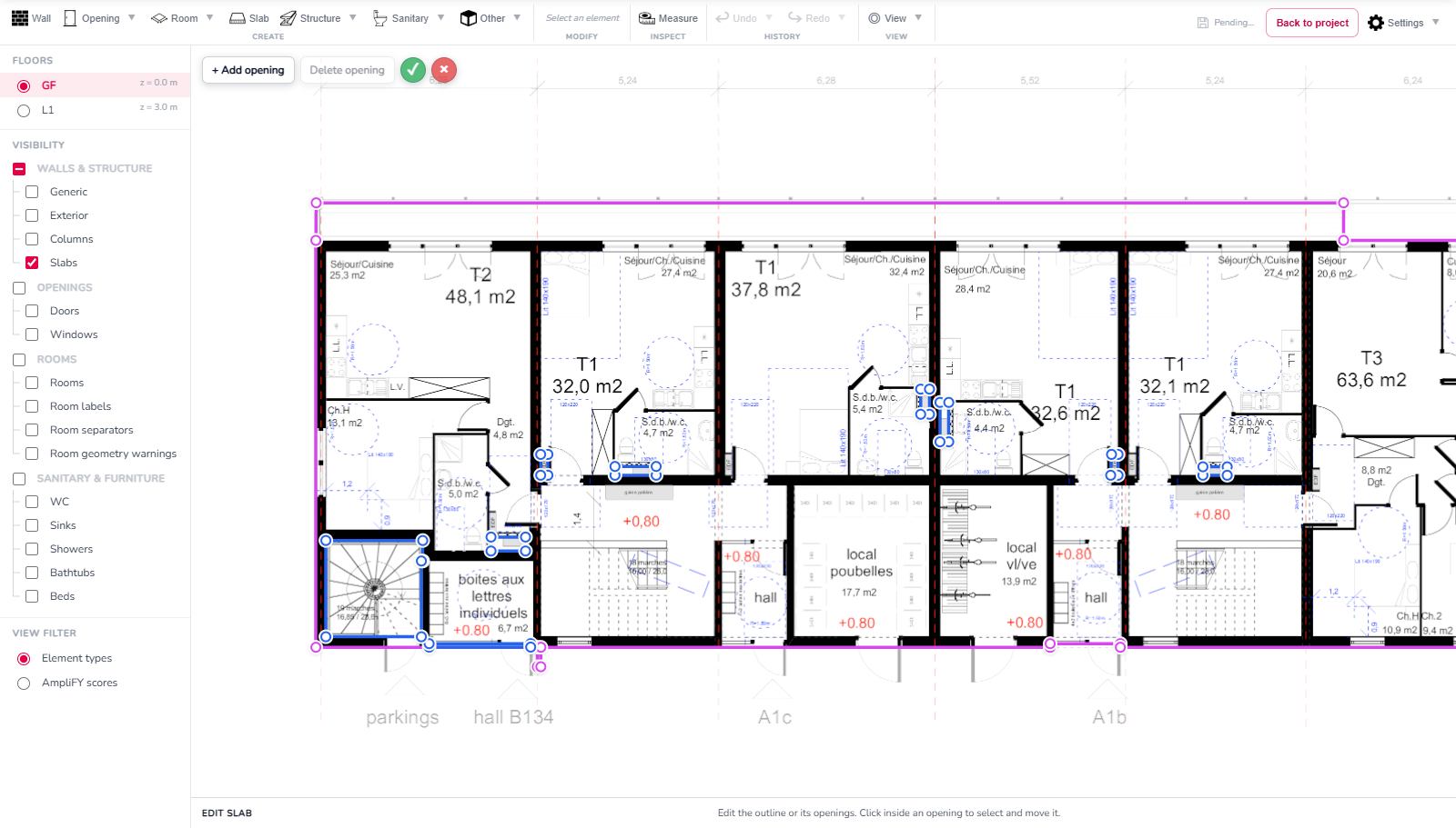
Select one slab and click “Edit slab”. Its boundary vertices become editable. Move vertices or edges to match the footprint; check that the outline remains valid.
- Delete a vertex: right-click it, or select it and press Delete. Each outline must retain at least three vertices.
- Keep orthogonal directions: hold Shift while dragging a single vertex to constrain its movement to the horizontal or vertical alignment guides.
- Edit openings: use “+ Add opening” to draw a hole, or select an existing opening to move, reshape or delete it.
Confirm with the check mark when finished, or cancel the changes with the cross.
A slab opening is a hole through the slab, not a door or window in a wall. Check it in 3D after editing, especially around stairs, lifts and shafts.
View menu
| Option | Effect |
|---|---|
| Fit all | Reframe the scene when you have zoomed or panned away from the model. |
| PNG floor plan | Adjust the source-plan opacity. The examples in this guide use 100%. |
| 3D modeled elements | Adjust model opacity to compare geometry with the underlying drawing. At zero opacity, the current selection stays visible in isolation; with no selection, the model is hidden. Increase opacity to restore the model. |
| Lines thickness | Adjust the displayed outline thickness for readability. This does not change a wall’s physical thickness. |
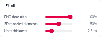
These controls affect display, not model geometry. Storey visibility, element-family filters and colour modes remain available in the side panels. Use “Settings” to choose the property shown in room labels.
Assign and create wall types
- Select a wall and open its Wall type field in the properties panel. Choose an existing wall type to assign it.
- To define a new type, choose “Add new wall type” at the bottom of the list. Enter a descriptive name, choose its colour and save. The new type is assigned to the selected wall.
- Use “Manage wall types” in the same list to rename types, change colours, add entries or delete eligible entries.
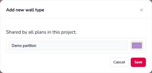
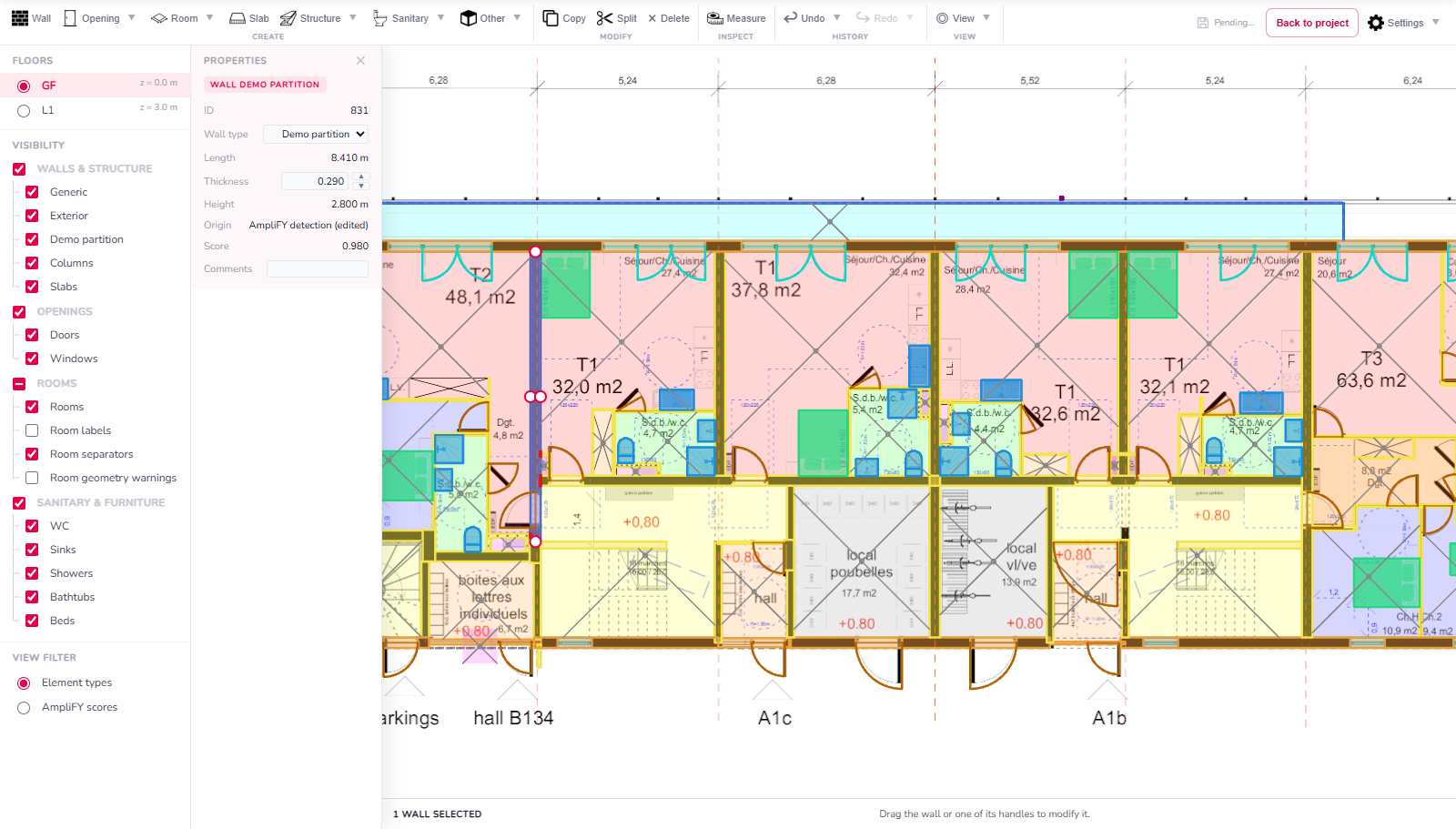
The list is shared across both storeys of this project. A type name and colour classify the wall; they do not by themselves define a layered construction or change its thickness. Set geometric properties separately. Deleting a type in use requires confirmation and reassigns its walls to the default type shown in the dialog; the protected default cannot be deleted.
Assign and create room categories
- Select a room and choose an existing category in its properties. Keep the room name, category and unit assignment distinct.
- Choose “Add new room category” to enter a name and colour, then save. The new category is assigned to the selected room.
- Open “Manage room categories” to maintain the shared project list. Changes apply across the project, including the other storeys.
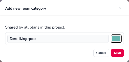
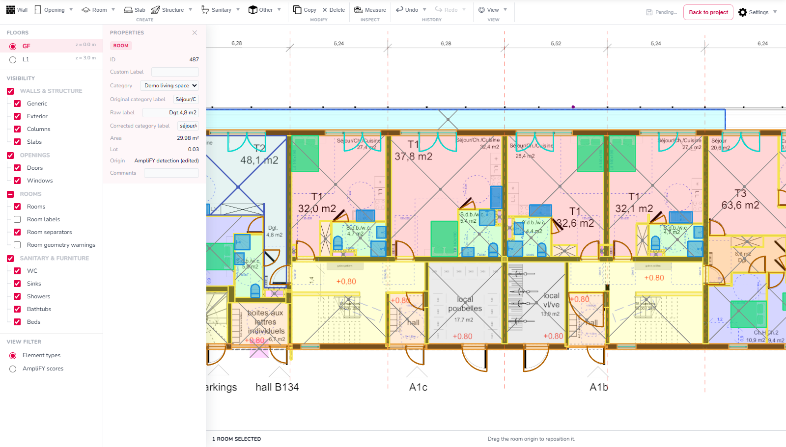
Deleting a category in use reassigns its rooms to the fallback shown in the confirmation. Changing a category does not redraw the room. Check room geometry warnings and resolve outline or overlap problems separately.
Choose room labels and understand recognised text
The room’s properties keep its display name, classification and recognised source text in separate fields. Select the cross marker to inspect or edit them.
| Field | Meaning |
|---|---|
| Custom Label | The room name you can customise, such as “Main bedroom”. It may initially contain a generated name. Editing it does not change the room’s Category. |
| Category | The classification selected from the project catalogue, such as Bedroom. It controls category-based naming and colouring. |
| Raw label | The source text associated with the room during recognition. Use it to compare the interpreted result with the plan. |
| Original category label | The category text read from the plan before text correction. |
| Corrected category label | The corrected category text produced during recognition. It remains separate from the Category selected in the catalogue. |
Recognition fields can be empty when no usable text was found. They can be edited, but changing their text does not automatically reclassify the room. Set Category explicitly when correcting the classification.
Open Settings → Room labels to choose what appears on the plan. Select Custom Label to display names such as “Main bedroom”, or Category + Area to display the category and the calculated area together. This changes the display only; it does not overwrite the room’s properties or geometry.
Geometry and snapping
Use the tool’s snapping cues and alignment constraints to place elements accurately. Shift constrains several operations horizontally or vertically; the exact controls depend on the active tool. Check “Settings → Keyboard shortcuts” when switching between tools.
Create a generic free shape
Use a generic free shape for an object with a custom footprint. Its outline belongs to that individual object.
- Open “Other → Generic (free shape)” and click on the plan to place the outline’s vertices. Add at least three points.
- Hold Shift while drawing to constrain the next segment horizontally or vertically. Delete or Backspace removes the last point.
- Click the first point again, or press Enter, to close the outline and create the object. Adjust its height and other properties in the properties panel.
While drawing, Escape clears the points; press it again to leave the tool. The generic object’s Model field displays “Free shape”. To remove the placed object, select it and press Delete outside outline-editing mode.
Use a free shape as an object’s Model
For supported object families, a free shape can also be a reusable custom model. The object keeps its family, while the custom outline defines its footprint.
- Select an object and open the Model field in the properties panel. Choose an existing custom shape to assign it, or choose “New free shape”.
- For a new shape, draw its footprint on the plan using the same drawing controls as above, then close the outline. The new model is assigned to the selected object, whose position and footprint dimensions follow the drawing.
- To reuse it, select another object of the same family and choose the custom model in its Model list. These models are shared across the project’s storeys.
Edit and manage free shapes
Edit an outline: double-click a generic free shape or an object using a custom free-shape model. Drag vertices to reshape it, or click an edge to insert a vertex. Right-click a vertex, or select it and press Delete, to remove it; keep at least three vertices. Hold Shift while dragging a single vertex to follow the orthogonal alignment guides. Validate with the check mark or discard the changes with the cross.
Editing a generic free shape changes that object only. Editing a custom model changes the shared shape for every object using that model, including on other storeys. Create a new model first if you need a separate variant.
Rename or delete a model: select an object of the relevant family and choose “Manage free shapes” from its Model list. Rename entries or mark them for deletion, then click Save to apply the changes. Undo restores an entry marked for deletion before saving; Cancel discards the pending changes.
Deleting a custom model restores the default model on all objects using it; the placed objects remain in the project. This list manages reusable models for the selected family. Individual generic free shapes are edited or deleted directly in the scene.
Delete, undo and redo
Delete removes the selected elements. Undo (Ctrl + Z) and Redo (Ctrl + Y) step through model edits; their history lists let you review recent operations. These controls differ from hiding an element in a display filter. After a wall change, check its openings and adjacent room boundaries before continuing.
11 · Deliverables
Export formats and file generation
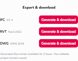
Under “Export & download”, choose a format and click “Generate & download”. Files are generated on demand; seeing the model on screen does not mean all exports are ready.
| Format | Use | Version shown in the interface |
|---|---|---|
| IFC | Share a structured model with a BIM environment that supports this format. | IFC4 |
| RVT | Continue modelling in a compatible Revit environment. | Revit 2022 |
| DWG | Use the drawings in a compatible CAD environment. | DWG 2018 |
When exporting an editable project, the application requests a save before preparing the export. If saving fails, resolve that issue before trying again. After further corrections, generate a new export to share the correct model state.
How the Revit model is built
The standard RVT export starts from an AmpliFY generic project template in Revit 2022 format, with an English or French version selected from the project’s generation language. AmpliFY creates a new model from this template using the project geometry, storey settings and supported element properties.
| Component | How it is constructed |
|---|---|
| Levels and plan views | Storey names and elevations define Revit levels and associated floor-plan views. Horizontal storey offsets position the plans and model geometry together. |
| Source-plan image | The cropped source plan is imported as a raster image in the corresponding floor-plan view, scaled and positioned to match the model. Even a vector PDF becomes an image here; its drawing lines are not imported as editable CAD lines. |
| Walls and wall types | Walls are native Revit walls. Types are created or reused for each project wall-type name and thickness, for example “Partition - 100 mm” and “Partition - 150 mm”. Their construction comes from a template wall type adjusted to the required thickness. Materials and layer build-ups are not inferred from the plan. |
| Doors, windows and objects | Supported elements use the generic families supplied in the template. The exporter selects family types and adjusts supported dimensions and orientation. Doors and windows are hosted by their walls. These families provide editable representations, without specifying a manufacturer or product. |
| Rooms and colours | Rooms are native Revit rooms, placed using their origin points. Room-separation lines are added where needed to enclose them. Category names populate the Department property; room colour schemes and wall view filters carry the project’s category and type colours. |
| Slabs and top closure | Floor slabs use the saved footprints and openings, with floor types sized to the storey slab thicknesses. The top closure is also created as a Revit floor slab on an additional roof level. |
In Revit’s Project Browser, open a storey’s floor-plan view to compare the model with its raster reference, then inspect the 3D model. Adapt families, materials, wall build-ups and view settings to your deliverable requirements. Room areas are calculated by Revit from its boundaries, so compare them with the reviewed AmpliFY areas.
Current limits of the standard Revit export
The editor’s Model choice and custom free-shape contours are not transferred as custom Revit families. A supported object using a free-shape model is represented by its generic family. Generic rectangles, generic free-shape objects, railings, kitchen units and stairs are currently omitted from this export. Check these elements before relying on the RVT deliverable.
Revit wall and column heights follow the storey constraints and slab thicknesses. Other objects use the supplied family’s height; changes to their Height field in the editor are not transferred. Openings edited in the top roof slab are also not currently reproduced. Inspect these cases in Revit and complete them there as needed.
Processing and export availability
IFC and RVT/DWG use different processing paths. RVT and DWG use the Revit generation pipeline; availability depends on processing and service load. The interface shows generation, download, failure and unavailability states.
If a credit confirmation appears, read the requested format and displayed balance. Conditions depend on your account and plan; this guide does not define prices or quotas.
Download files as soon as they are ready.
The export screen states that generated files remain available for 2 hours. This applies to temporary deliverables; your saved editable project remains accessible separately. After expiry, reopen the project and regenerate the files if your access allows it.
After downloading, open the file in your target software and check units, levels, geometry and expected elements. The browser view and the target application’s display can differ.
12 · Model validation
Checks before exporting the model
Check each storey, then the assembled building.
- One or more model lengths agree with dimensions on the plan.
- The building perimeter is complete and important walls are continuous.
- Doors and windows are present, correctly placed and correctly sized.
- Rooms have consistent outlines, meaningful names and appropriate categories.
- Slabs cover the correct areas and their openings are justified.
- Required objects are present, correctly oriented and correctly sized.
- Storeys are in the correct order, at the correct elevations and horizontally aligned.
- Heights and window sill heights match the project assumptions.
- Low-scoring areas have been reviewed and corrections are saved.
- The latest export opens correctly in the target software.
13 · Frequently asked questions
Diagnose errors and troubleshoot
Dimensions or areas are too large or too small.
Check the scale and calibration distance. Compare a long document dimension with the model measurement. If the error affects the whole plan, repeat calibration and generation before making local corrections. If it varies by area, the scan may be distorted.
Part of the building is missing, or no building is detected.
Check the building area, selected page and file readability. An overly tight frame can exclude elements; a cluttered or poor-quality plan can hinder detection. Prepare a clearer source and import it again.
Walls, doors or rooms are reconstructed incorrectly.
Inspect the source plan and scale first, then correct elements in the editor. Dense hatching, double lines, unusual symbols and overlaps can cause omissions or confusion. Check neighbouring elements after making corrections.
Room names are missing or incorrect.
Text recognition can fail independently of geometry. Check label clarity and correct names or categories in the properties. Text that looks readable in a PDF may only be an image to the processing engine.
Heights do not match the real building.
Check generation preferences, then project elevations and properties. Default vertical values supplement the 2D plan; they are not an automatic survey of actual heights.
Storeys do not overlap correctly.
Check their order and scale first. Then use “Align storeys” with common reference points far apart. If only one point aligns, investigate differences in scale or orientation. Check upper levels after each move.
The model disappeared during inspection.
Reset the camera and check the active storey, category visibility and opacity sliders. Hidden geometry remains in the project.
The editor reports unsaved changes.
Keep the tab open, check your connection and read the message associated with the indicator. Wait for “Saved” before leaving. If the error persists, note the project name, time and message when requesting help.
A download is unavailable, slow or failing.
Distinguish ongoing generation from an explicit failure. Check account access, any credit confirmation and format availability. RVT/DWG may take longer. If a file has expired, regenerate it from the saved project.
Can I use AmpliFY for any building type?
The workflow focuses on residential plans. Other building uses, unusual drawing conventions or very complex buildings can fall outside well-recognised cases. Validate a representative plan and inspect the result before processing an entire set of documents.
Does the model describe every construction detail?
The result contains elements recognised, reconstructed or added in the editor. Its appearance does not imply that materials, wall build-ups, building services or details absent from the plan have been specified. Complete the model in your specialist tools according to the required deliverable.
To report an issue, provide the project name, affected step, displayed message and a description of the expected result. Contact support@ify.solutions.